10-20 system: EEG electrode placement step by step
EEG electrode placement with the 10-20 system: nasion–inion measurement, the 19 electrodes and their regions, T3 vs T7, where Cz is, and 10-10 and 10-5.
Published
The 10-20 system is the international standard that defines where EEG electrodes sit on the scalp as percentages of the distances between four anatomical landmarks. Published by Herbert Jasper in 1958 on behalf of the International Federation (today’s IFCN), it lets recordings made in different laboratories, on heads of different sizes, be compared under the same names: when a paper says “the P300 was measured at Pz”, the reader knows where the electrode was. This guide covers what the 10 and the 20 mean, how the measurement is made step by step, how electrode names are read, the difference between old and new names such as T3 and T7, the 10-10 and 10-5 systems developed for high-density caps, and the limits of the system, all from the point of view of research methodology.
What do the 10 and the 20 mean?
The system takes its name from the spacing between electrodes. Two reference lines are measured on the head first: the front-to-back line between the nasion at the root of the nose and the inion at the back of the skull, and the left-to-right line between the preauricular points in front of the ears. Electrodes sit 10% of a line’s total length in from its ends and 20% of its length from one another. The front-to-back line is thus divided into six parts of 10%, 20%, 20%, 20%, 20% and 10%, which add up to 100%.
The strength of the approach is that positions are defined by proportion, not by centimetres. On a small head the electrodes sit closer together and on a large head further apart, but each electrode falls on the same relative point of the skull in every participant. This is why the 10-20 system is described as a “relative head-surface-based positioning system” (Jurcak et al., 2007). The classic layout has 21 positions: 19 recording electrodes and two reference electrodes on the earlobes (A1 and A2).
The four anatomical landmarks
The accuracy of the measurement depends on finding the landmarks correctly. They are located by touch (palpation) and marked with a skin pencil. Four are measured; a fifth is calculated from them.
- Nasion
- The depression between the eyes where the frontal bone meets the nasal bones (the root of the nose). It is where the front-to-back line begins.
- Inion
- The most prominent point of the external occipital protuberance (protuberantia occipitalis externa) at the back of the head: the bony bump felt just above where the neck muscles begin.
- Left and right preauricular points
- The depression at the root of the cheekbone, just in front of the small cartilage flap in front of the ear (the tragus). They are the two ends of the left-to-right line.
- Vertex (Cz)
- A point that is calculated rather than measured: where the midpoint of the nasion–inion line crosses the midpoint of the line between the two preauricular points. It is the top of the head and the centre of the whole layout.
Definitions of the preauricular point can differ by a few millimetres between laboratories; some teams use the tragus itself or the entrance of the ear canal. Jurcak and colleagues (2007) showed that the rule used to set the landmarks affects the spread of electrode positions, and that positions can be found consistently when a detailed rule is followed. What matters is that the laboratory chooses one definition, writes it into its protocol and applies it the same way to every participant.
Measuring and marking, step by step
The classic measurement takes a flexible tape measure, a skin pencil and a few minutes of care. The sequence below gives all 19 recording positions, and each step includes a check on the one before.
- Find and mark the nasion, the inion and the two preauricular points.
- Measure the distance from nasion to inion along the midline over the top of the head. Starting from the nasion, mark Fpz at 10%, Fz at 30%, Cz at 50%, Pz at 70% and Oz at 90%. Oz therefore lies 10% above the inion.
- Measure between the two preauricular points, passing over the Cz mark from the previous step. The midpoint of this line should fall on the midpoint of the front-to-back line; where the two midpoints meet is the definitive Cz position. Starting from the left, mark T7 at 10%, C3 at 30%, Cz at 50%, C4 at 70% and T8 at 90%.
- Measure the head circumference through Fpz, T7, Oz and T8. Each half circumference from the front midline point to the back midline point is divided in the same proportions: on the left, Fp1 falls at 10% of the half circumference, F7 at 30%, T7 at 50%, P7 at 70% and O1 at 90%. On the right, Fp2, F8, T8, P8 and O2 are found the same way. Finding T7 and T8 again here is the check on the third step.
- F3 lies at the midpoint of the line between Fz and F7 and, at the same time, at the midpoint of the line between Fp1 and C3; mark the point where the two measurements cross. F4, P3 and P4 are found the same way: P3, for example, lies midway between Pz and P7 and midway between C3 and O1.
- Compare matching distances on the left and right (for example Fp1–F7 against Fp2–F8). If there is a clear asymmetry, check the landmarks again and repeat the measurement.
- Write the nasion–inion length, the preauricular distance and the head circumference into the participant record. These values are used to choose the cap size, to place electrodes in the same positions in repeated sessions and to write the methods section.
Once the positions are marked, skin preparation and the impedance check follow. These steps depend on the electrode type (wet, dry or active) and are covered separately in the guide “How is EEG recorded?”.
Letters and numbers: how to read electrode names
Every electrode name consists of one or two letters followed by a number or by the letter “z”. The letter gives the region the electrode sits over; the number or the z gives its position relative to the midline. Once the rule is learnt, a glance at a channel list tells you where on the head each electrode sits.
- Fp
- Frontopolar (prefrontal): the very front of the forehead, just above the eyebrows.
- F
- Frontal: the region between the forehead and the top of the head.
- C
- Central: not the name of a lobe. It refers to the area around the central sulcus (sulcus centralis), which separates the frontal and parietal lobes, that is, over the sensorimotor cortex.
- T
- Temporal: above and around the ears.
- P
- Parietal: the back part of the top of the head.
- O
- Occipital: the back of the head, above the inion.
- A
- Auricular: the earlobes (A1 left, A2 right). In the classic layout they are mostly used as reference electrodes.
- z
- Zero: the midline electrodes, namely Fpz, Fz, Cz, Pz and Oz.
- Odd and even numbers
- Odd numbers are on the left hemisphere, even numbers on the right. The larger the number, the further the electrode lies from the midline: F3 is closer to the midline than F7.
The table below shows the classic 19 recording positions. The second column gives the old name of the four positions renamed in the 10-10 nomenclature; “—” means the name has not changed.
| Electrode | Old name | Region | Hemisphere |
|---|---|---|---|
| Fp1 | — | Prefrontal (frontopolar) | Left |
| Fp2 | — | Prefrontal (frontopolar) | Right |
| F7 | — | Frontal (lateral) | Left |
| F3 | — | Frontal | Left |
| Fz | — | Frontal | Midline |
| F4 | — | Frontal | Right |
| F8 | — | Frontal (lateral) | Right |
| T7 | T3 | Temporal (mid) | Left |
| C3 | — | Central | Left |
| Cz | — | Central (vertex) | Midline |
| C4 | — | Central | Right |
| T8 | T4 | Temporal (mid) | Right |
| P7 | T5 | Temporal (posterior) | Left |
| P3 | — | Parietal | Left |
| Pz | — | Parietal | Midline |
| P4 | — | Parietal | Right |
| P8 | T6 | Temporal (posterior) | Right |
| O1 | — | Occipital | Left |
| O2 | — | Occipital | Right |
Region names are shorthand for the area of the skull beneath the electrode. They do not mean that the signal an electrode records belongs to that lobe alone; the last section returns to this.
Old and new names: why did T3 become T7?
In Jasper’s layout the temporal electrodes were named T3, T4, T5 and T6. These names contradicted the system’s own logic: F7, T3 and T5 stood on the same sagittal line yet carried different numbers, while the letter “T” appeared on two separate coronal lines. The “modified combinatorial nomenclature” that came with the 10-10 system made it a rule that each letter appears on only one coronal line and each number on only one sagittal line. The guideline of the American Clinical Neurophysiology Society (ACNS) summarises the change as follows (Acharya et al., 2016):
- T3 → T7: left mid-temporal
- T4 → T8: right mid-temporal
- T5 → P7: left posterior temporal
- T6 → P8: right posterior temporal
The electrodes have not moved; only their names have changed. F7, T7 and P7 now line up on the same sagittal line with the same number, and the positions 10% below that row are easily named F9, T9 and P9. The guideline accepts that it is counter-intuitive for P7 and P8, which lie over the temporal region, to carry the letter “P”, and suggests a reading rule: when P is followed by a number of 6 or less the electrode is parietal; when it is followed by 7 or more it is posterior temporal.
In practice both nomenclatures live side by side. The ACNS guideline sees the move to the new names as the desirable direction but, for now, finds it acceptable to keep using T3/T4 and T5/T6, or to write both names together. Keep the mapping in mind when reading an older paper, a clinical recording or a device’s channel list. When combining data from different sources or choosing a montage file, make sure channel names follow the same nomenclature; otherwise one position can appear as two separate channels.
10-10 and 10-5: extensions for high-density caps
Nineteen electrodes are sparse for topographic maps and source analysis. The 10-10 system, proposed in 1985, adds new rows between the existing lines at 10% intervals. Intermediate rows take their names from the letters of the two neighbouring rows, and the numbers follow the same sagittal-line rule: AF3, FC3, CP3 and PO3, for example, lie on one line.
- AF: between the frontopolar and frontal rows (anterior frontal)
- FC and FT: between the frontal and central rows, and between the frontal and temporal rows
- CP and TP: between the central and parietal rows, and between the temporal and posterior temporal rows
- PO: between the parietal and occipital rows
- F9/F10, T9/T10, P9/P10: positions 10% below the lateral row
According to the ACNS guideline, the 10-10 system defines more than 70 positions, and using all of them is most valuable for advanced analyses such as source localisation and electrical source imaging. Oostenveld and Praamstra (2001) proposed the 10-5 system, which divides the 74-electrode extended 10-20 layout at 5% intervals to define up to 345 positions; it was designed for high-resolution EEG and ERP recordings with 128 or more channels. The 10-5 system has not been adopted as a standard by the ACNS or the IFCN, but it is used in research caps and in the template montages of analysis software.
There is a limit to how dense positions can get. In an analysis of MR images by Jurcak and colleagues, 10-10 positions were well separated on the scalp, whereas 241 of the 329 positions examined in the 10-5 system could be placed without overlapping a neighbour. In other words, 5% spacing approaches the limit of how far positions on real heads can be told apart.
| System | Spacing | Number of positions | Typical use |
|---|---|---|---|
| 10-20 | 10% and 20% | 21 (19 recording electrodes and 2 earlobes) | Routine EEG, low-channel research and BCI recordings |
| 10-10 | 10% | More than 70 (74 in the extended layout) | Typically 32–64-channel research caps, ERP topography |
| 10-5 | 5% | Up to 345 | High-resolution EEG with 128 channels or more, source analysis |
Why measure even with a ready-made cap?
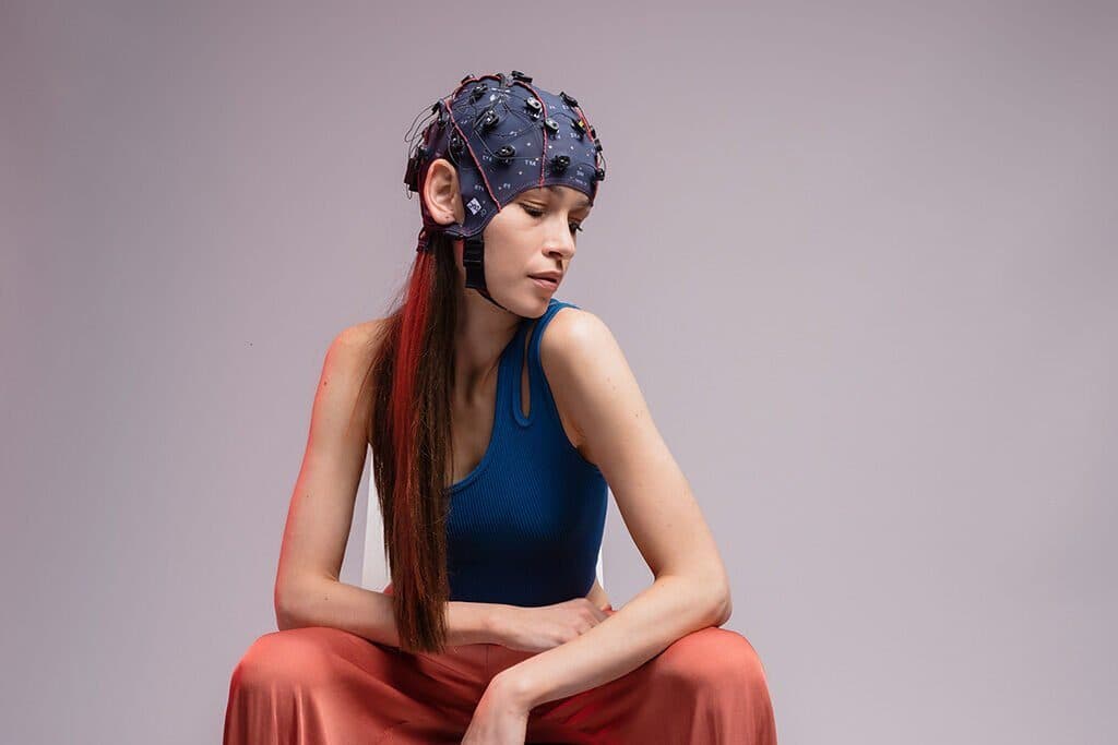
Most research laboratories today use elastic caps with pre-set electrode positions. A cap distributes the 10-20 or 10-10 positions according to a particular head shape; for that distribution to be right, the cap must be the right size and be placed correctly. g.GAMMAcap caps, for example, offer 74 labelled and 86 intermediate positions based on the extended 10-10 system, and adult sizes are divided by head circumference into 50–54, 54–58 and 58–62 cm. If the size is too small or too large, or the cap slips a few centimetres forward, every electrode lands in the wrong place together.
- Measure the head circumference and choose the size accordingly.
- Measure the nasion–inion distance and mark its midpoint (the vertex); check it against the preauricular line.
- Place the cap so that the Cz electrode sits exactly over this mark.
- Check that the front-row electrodes, Fp1 and Fp2, sit roughly 10% of the nasion–inion distance above the nasion.
- Make sure the cap’s midline runs along the line joining nasion and inion and that the cap is not rotated to the left or right; compare the distance of matching electrodes on each side to the ears.
- Fasten the chin strap so that the cap cannot slip but the participant is not uncomfortable.
In studies that involve source analysis, or where electrode positions are matched to an individual MR image, template positions are not enough. Analysis software such as MNE-Python provides ready-made template montages named after the 10-20, 10-10 and 10-5 systems, but these are idealised positions based on an average head model. In such studies the actual position of each electrode, once the cap is on, is recorded with a 3D digitiser or by photogrammetry, and the analysis uses those positions.
Limits: an electrode position is not a source location
The 10-20 system places an electrode on a point of the skull, not on a region of the brain. The relationship between skull and cortex varies from person to person. Koessler and colleagues (2009) used MRI in 16 healthy participants to study how 10-10 positions project onto the cortex, and found standard deviations of 4.6 mm on the x axis, 7.1 mm on the y axis and 7.8 mm on the z axis. Variability was greatest in the central and parietal regions and smallest in the frontal and temporal regions.
The second limit comes from the signal itself. The potential an electrode records is the sum of the cortex beneath it and of distant sources reaching it by volume conduction, and it changes with the choice of reference. “Activity seen at electrode C3” therefore does not mean the same thing as “activity from the left motor cortex”. Drawing conclusions about sources requires high-density recordings, recorded electrode positions and a head model, and the methods section should state this difference between electrode name and anatomical region clearly.
Despite these limits, 10-20 positions are a reproducible way to reach regions of the brain approximately, and the same layout serves as a reference for placing fNIRS optodes and the TMS coil. In clinical EEG, which electrodes to use and how to interpret the recording depend on a physician’s assessment; this guide is written from the point of view of research methodology.
Caps made to the 10-20 and 10-10 layouts, active and passive electrodes and the amplifiers they work with are in the catalogue. For cap size, channel count and electrode type for your laboratory, you can reach us through the quote form.
Explore the map
Select an electrode on the map to see its name, region and hemisphere; switch on the measurement lines to follow the 10% and 20% steps along the nasion–inion line and the line between the two preauricular points.
Select an electrode to see its name, region and hemisphere.
Cz
Over the motor and somatosensory cortex. C3, Cz and C4 are the core channels of motor-imagery BCI studies.
The letter gives the region, the number the hemisphere: odd numbers left, even numbers right; z (zero) is the midline.
Frequently asked questions
What is the 10-20 system?
The 10-20 system is the international standard that defines EEG electrode positions as percentages of the distances between the nasion, the inion and the two preauricular points. Electrodes sit 10% in from the ends of these lines and 20% apart from one another. The classic layout has 19 recording electrodes and two reference electrodes on the earlobes.
Where is Cz and how do you find it?
Cz is at the top of the head (the vertex). It is the point where the midpoint of the nasion–inion distance crosses the midpoint of the distance between the two preauricular points. When a ready-made cap is used, the Cz electrode is placed over this measured point.
What is the difference between T3 and T7?
Only the name differs; the electrode is in the same place. T3 and T4 in the old 10-20 nomenclature are T7 and T8 in the 10-10 nomenclature, and T5 and T6 are P7 and P8. The ACNS guideline recommends the new names but, for now, also finds it acceptable to use the old names or both together.
What is the difference between the 10-20 and 10-10 systems?
The 10-10 system adds new rows at 10% intervals between the 10-20 lines and defines more than 70 positions; the intermediate rows are named with the letters AF, FC, FT, CP, TP and PO. The classic 19 positions are in the same place in both systems. High-channel research caps are laid out on 10-10 positions or on the denser 10-5 positions.
What do the letters and numbers on EEG electrodes mean?
The letter gives the region: Fp frontopolar, F frontal, C central, T temporal, P parietal, O occipital, A earlobe. Odd numbers mark the left hemisphere, even numbers the right, and the letter “z” the midline. The larger the number, the further the electrode is from the midline.
Do you still need to measure when using a ready-made EEG cap?
Yes. A cap distributes positions for a particular head shape; for a correct result, choose the size that fits the head circumference and place the Cz electrode over the measured vertex. A slip of a few centimetres shifts every electrode together. If source analysis is planned, the actual positions are digitised as well.
References and further reading
- Acharya et al. (2016) · ACNS Guideline 2: Guidelines for Standard Electrode Position Nomenclature · J Clin Neurophysiol
- Oostenveld and Praamstra (2001) · The five percent electrode system for high-resolution EEG and ERP measurements · Clin Neurophysiol
- Jurcak, Tsuzuki and Dan (2007) · 10/20, 10/10, and 10/5 systems revisited · NeuroImage
- Koessler et al. (2009) · Automated cortical projection of EEG sensors: anatomical correlation via the international 10–10 system · NeuroImage
- MNE-Python · Working with sensor locations